AWG Wire Gauge Quick Reference
| AWG | Max Amps (chassis wiring) | Resistance (ohms per 1000 ft) | Typical Use |
|---|---|---|---|
| 4/0 (0000) | 230 | 0.0490 | Large inverter banks, 12V systems over 2000W |
| 2/0 (00) | 175 | 0.0779 | Mid-size 12V inverters, 24V systems over 3000W |
| 1/0 (0) | 150 | 0.0983 | 24V inverter connections, large trolling motors |
| 2 | 115 | 0.156 | 24V inverters under 2500W, 48V systems |
| 4 | 85 | 0.248 | 48V inverters, smaller 12V inverters under 1000W |
| 6 | 65 | 0.395 | 48V systems under 3000W, short 24V runs |
| 8 | 50 | 0.628 | Small loads, charge controllers under 30A |
| 10 | 35 | 0.999 | Solar panel home runs, small DC circuits |
These are approximate ampacity ratings for copper wire at 30C ambient. Higher temperatures, bundled wires, or conduit runs require derating. When in doubt, go one size larger. The extra cost of heavier wire is trivial compared to replacing a melted cable or dealing with a fire.
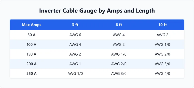
How to Size Your Inverter Cables
- Calculate the DC current. Divide inverter watts by battery voltage. A 3,000W inverter on 12V = 250A. On 24V = 125A. On 48V = 62.5A. This is why higher voltage systems are easier and cheaper to wire.
- Set your voltage drop target. 3% is the standard maximum for DC power cables. On a 12V system, 3% is only 0.36V — there is very little room for error. Tighter targets (2%) need bigger wire but protect your inverter from low-voltage shutoffs.
- Measure the cable run. Measure from the battery terminal to the inverter terminal. The calculator accounts for the round trip (positive and negative cable), so enter the one-way distance only.
- Check the result against ampacity. The recommended gauge must handle the full current without overheating AND keep voltage drop under your target. Sometimes voltage drop demands a larger wire than ampacity alone would require — especially on long runs at 12V.
- Use the correct cable type. For battery-to-inverter connections, use fine-stranded welding cable or marine-grade battery cable. Solid-core house wire (Romex) cannot handle the vibration and flexing that battery cables experience. Our inverter cable sizing guide covers cable type selection and installation best practices.
Example: Cabling a 3,000W Inverter at 12V
A common off-grid RV setup: 3,000W pure sine inverter, 12V lithium battery bank, 6 feet from battery to inverter.
DC current: 3,000W / 12V = 250A. At 3% max drop over 6 ft: you need 4/0 AWG cable minimum. That is thick, heavy, and expensive — about $8-12 per foot for quality welding cable.
If you move to a 24V system, the same 3,000W inverter draws only 125A. Now 2/0 AWG handles it comfortably at the same distance. The cable costs roughly half, weighs half, and is much easier to route through tight spaces.
This is exactly why experienced off-grid builders prefer 24V or 48V systems. The inverter costs about the same, but the cabling savings and reduced voltage drop make the entire installation simpler and safer. If you are designing a new system from scratch, consider 24V as the minimum — our solar panel and battery sizing calculator can help you design the complete system.
Worked Examples
Wiring a 3000W Inverter in a Camper Van
Context
You are mounting a 3,000W pure-sine inverter in a camper van. The battery bank is 12V and the cable run from batteries to inverter is 5 feet one way (10 feet round trip).
Calculation
Current draw = 3,000 W / 12 V = 250 A
250A is more current than a single 4/0 AWG conductor can safely carry: 4/0 copper is rated 230A at 75°C (NEC 310.16). The calculator returns "Larger than 4/0" — no single prescriptive conductor fits this load. You would need parallel conductors (two 1/0 cables sharing the current, per NEC 310.10(H)) or, far better, a higher system voltage.
Interpretation
This is the headline lesson of 12V high-power systems: 250A is welding-cable territory and beyond what one battery-to-inverter cable should carry. Ampacity, not voltage drop, is the binding limit here. Pushing 250A through a single undersized cable generates dangerous heat and risks a DC fire.
Takeaway
Shortening the run does not help: distance changes voltage drop, not ampacity, so 250A still exceeds a single 4/0 at any length. The real fix is a higher-voltage bank — the same 3,000W inverter draws 125A at 24V (within a single 1/0) and just 62.5A at 48V. To check how long this inverter runs your loads, use our battery runtime calculator with the total wattage of what you are powering.
Upgrading to 48V to Save on Cable Costs
Context
An off-grid cabin has a 5,000W inverter on a 12V battery bank. The cable run is 15 feet. The owner is considering switching to a 48V bank to reduce cable costs.
Calculation
At 12V: 5,000 / 12 = 416.7 A — far beyond a single 4/0 conductor (230A max), so the 12V build needs multiple paralleled cables, which is impractical and costly.
At 48V: 5,000 / 48 = 104.2 A — a single 2 AWG cable handles it (rated 115A at 75°C), at a few dollars per foot.
The 48V build replaces an awkward parallel-cable run with one pencil-thick conductor.
Interpretation
Quadrupling the voltage cuts current to one quarter. At 12V the 416A load exceeds any single conductor; at 48V it drops to a single 2 AWG cable, which is dramatically easier to route and terminate.
Takeaway
Moving to 48V is the single biggest cost-saving decision in off-grid wiring. To size the battery bank at 48V, use our solar battery bank size calculator — it accounts for autonomy days and depth of discharge.
Frequently Asked Questions
Glossary
Voltage Drop
The loss of voltage across a length of cable due to its electrical resistance. On low-voltage DC systems (12V, 24V), even small resistance causes large percentage drops, which reduces the power available at the inverter.
Round-Trip Distance
The total cable length from battery positive terminal to inverter and back through the negative terminal. Always double the physical distance between battery and inverter when calculating voltage drop.
Cable Gauge
A standardized measurement of wire thickness (AWG in the US). Larger gauge numbers mean thinner wire. Thicker cables have lower resistance and handle more current, but cost more and are harder to route through tight spaces.
Figuring out what size battery bank you need for the inverter? Our battery size for inverter calculator matches battery capacity to your power needs.
Related calculators
Battery Size for Inverter Calculator
Find the right battery capacity for your inverter. Enter load, runtime, and voltage for a proper battery sizing estimate.
Battery
Voltage Drop Calculator
Calculate voltage drop in any wire run. Enter wire gauge, distance, current, and voltage to check if your wiring meets NEC standards.
Electrical
Wire Distance Calculator
Calculate voltage drop and recommended wire gauge for any distance. Enter amps, distance, voltage, and target drop percentage.
Electrical
What Size Inverter for a 1500W Heater?
Size an inverter, battery bank, and solar array to run a 1500W space heater off-grid. Complete system sizing in one tool.
Solar
This calculator uses copper resistivity at 25°C (10.8 Ω·cmil/ft), which is standard for voltage drop estimation. At full conductor operating temperature (75°C), actual voltage drop will be 10-15% higher. For critical circuits operating near the maximum voltage drop limit, consider upsizing one gauge. DC cable sizing is one of the most safety-critical decisions in any battery-powered system. Unlike AC circuits protected by your home breaker panel, DC systems rely on properly sized fuses at the battery terminal and correctly rated cables. When in doubt, go one gauge larger. The extra cost is negligible compared to the consequences of an undersized cable. For permanent installations, have a licensed electrician review your wiring plan.
More Electrical calculators
Browse all electrical calculators — Motor FLA, wire sizing, voltage drop, load calculations, and transformer fusing based on NEC standards.
Last updated:
Written and maintained by Dan Dadovic, Commercial Director at Ezoic Inc. & PhD Candidate in Information Sciences. He works professionally as Commercial Director at Ezoic Inc., leading revenue strategy across digital publishing.
Disclaimer: Calculator results are estimates based on theoretical formulas. Actual performance varies with temperature, battery age, load patterns, and equipment condition. For critical electrical work, consult a licensed electrician.
Editorial review by Doc. dr. sc. Danijel Jerković-Štil, Assistant Professor, FERIT Osijek.