How to Size Inverter Cable
Last updated:
7 min read
The cable between your battery and inverter carries the highest current in your entire system. A 2,000W inverter on a 12V battery draws up to 185A through those cables — more than most household circuit breakers are rated for. Undersized inverter cable causes voltage drop that wastes energy, generates heat, and can melt insulation or start a fire.
This guide shows you how to select the right cable gauge for any inverter setup, from a small 500W unit in an RV to a 5,000W off-grid system.
Why Inverter Cable Sizing Matters More Than Other Wiring
In a standard household 120V AC circuit, a 2,000W load draws about 17A. The same 2,000W load on a 12V DC battery bank draws 167A — almost 10 times the current. Higher current means higher resistive losses (I²R losses), more heat generation, and larger voltage drop across the cable.
Voltage drop matters because your inverter needs a minimum input voltage to operate. Most 12V inverters shut down below 10.5V. If your battery is at 12.5V and your cables drop 1.5V at full load, the inverter sees 11.0V — close to shutdown. And those 1.5V of drop represent wasted energy: at 167A, that is 250W of heat being generated in your cables. That heat can melt PVC insulation, damage connectors, and create fire risk in enclosed spaces.
The NEC recommends keeping voltage drop below 3% for branch circuits. For battery-to-inverter cables, most manufacturers and experienced installers target 2% or less, because the inverter performs best with minimal voltage sag. Use the inverter cable size calculator for a quick answer tailored to your specific setup.
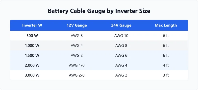
AWG Cable Rating Chart
This chart shows the maximum recommended current for common cable gauges used in DC battery systems, based on NEC Table 310.16 ampacity ratings for 75°C copper conductors. For inverter cable sizing, derate by 20% from the table value to keep the cable cool and minimize voltage drop.
| AWG | NEC Ampacity (75°C) | Derated for Inverter Use | Suitable Inverter Size (12V) | Suitable Inverter Size (24V) |
|---|---|---|---|---|
| 8 AWG | 50A | 40A | up to 400W | up to 800W |
| 6 AWG | 65A | 52A | up to 500W | up to 1,000W |
| 4 AWG | 85A | 68A | up to 700W | up to 1,400W |
| 2 AWG | 115A | 92A | up to 1,000W | up to 2,000W |
| 1/0 AWG | 150A | 120A | up to 1,300W | up to 2,600W |
| 2/0 AWG | 175A | 140A | up to 1,500W | up to 3,000W |
| 3/0 AWG | 200A | 160A | up to 1,800W | up to 3,600W |
| 4/0 AWG | 230A | 184A | up to 2,000W | up to 4,000W |
These ratings assume a cable length of 3 feet or less between battery and inverter. For longer runs, size up — every additional foot of cable adds resistance that increases voltage drop and heat. Use the wire distance calculator to account for cable length in your sizing.
Notice how 24V systems need much thinner cable than 12V for the same inverter wattage. A 2,000W inverter on 12V needs 4/0 AWG cable — expensive and stiff. The same inverter on 24V needs only 2 AWG — cheaper and much easier to route. This is one of the strongest practical arguments for choosing 24V or 48V system voltage when building a new installation. Our voltage drop guide explains the physics behind why higher voltage means lower current and smaller wire.
Step-by-Step Cable Sizing Process
Follow these five steps to select the right cable gauge for your battery-to-inverter connection.
- Find the maximum DC current. Divide your inverter's continuous wattage by the battery voltage: Current (A) = Watts / Voltage. A 2,000W inverter on 12V: 2,000 / 12 = 167A. On 24V: 2,000 / 24 = 83A. The amps draw calculator handles this conversion for any wattage and voltage.
- Add margin for surge. Most inverters can deliver 2x their rated power for a few seconds to handle motor startup surges (and note that inverter ratings in kVA vs kW affect what they can actually deliver to motor loads). While the cable does not need to handle surge current continuously, the cable must not overheat during 5-10 second surges. The 20% derate built into the chart above provides adequate surge margin for cables under 6 feet.
- Measure your cable run. Measure the one-way distance from battery positive terminal to inverter positive input. Double it for the total circuit length (positive cable + negative cable). A battery 3 feet from the inverter has a 6-foot total cable run. Keep this distance as short as possible — under 6 feet is ideal.
- Calculate voltage drop. Voltage drop = (Current × Cable length × Resistivity) / Cable area. For copper at room temperature, each AWG has a known resistance per foot. Target less than 2% drop: for a 12V system, that is 0.24V maximum. For a 24V system, 0.48V maximum.
- Select the larger of the two requirements. You need cable that satisfies both the ampacity requirement (current capacity without overheating) and the voltage drop requirement (less than 2%). For short runs under 3 feet, ampacity usually governs. For longer runs, voltage drop may require a larger gauge than ampacity alone would dictate.
Example: Sizing Cable for a 2,000W Inverter
Setup: 2,000W pure sine wave inverter, 12V LiFePO4 battery bank, 4-foot distance between battery and inverter (8-foot total cable run for positive and negative).
- Step 1: Maximum continuous current = 2,000 / 12 = 167A
- Step 2: From the AWG chart, 167A exceeds the derated capacity of 3/0 AWG (160A) but is within 4/0 AWG (184A). Use 4/0 AWG.
- Step 3: Verify voltage drop. 4/0 AWG copper has a resistance of about 0.0000501 ohms per foot. Over 8 total feet: 0.0000501 × 8 = 0.000401 ohms. Voltage drop = 167A × 0.000401 = 0.067V. That is 0.53% — well under the 2% target.
Result: 4/0 AWG copper cable, 4 feet each for positive and negative. Use ring terminals crimped with a hydraulic crimper (not a hardware store hand crimper) and rated for the cable gauge. Cover exposed terminals with heat shrink.
If this cable size seems impractical (4/0 is nearly 1/2 inch diameter and quite stiff), the solution is to increase system voltage. The same 2,000W inverter on 24V draws only 83A, which 2 AWG handles easily — a cable that is about 1/4 inch diameter and much easier to work with.
Cable Types and Safety Considerations
Use welding cable or marine-grade battery cable. Both are designed for high-current DC applications and have flexible stranding that makes routing easier. Standard THHN house wire is rated for the current but is solid or semi-solid core — too stiff to route in tight battery compartments and prone to fatigue failures from vibration (important in RV and marine applications).
Fuse the positive cable at the battery. Every positive cable leaving a battery bank must have a fuse or circuit breaker sized slightly above the maximum expected current. For the 2,000W/12V example: use a 200A Class T fuse within 6 inches of the battery terminal. This protects against short circuits that could weld connectors, melt cable, and start fires. The fuse is your last line of defense — do not skip it.
Torque lugs to specification. Loose connections create resistance, which creates heat. Most battery terminal lugs specify a torque of 12-15 ft-lbs. Use a torque wrench, not just "tight enough." Re-check connections after the first month of use — thermal cycling can loosen initially tight connections.
Separate positive and negative runs. Do not bundle positive and negative cables together in the same conduit or cable tie. If a short circuit develops, the physical separation prevents the fault from involving both conductors simultaneously. This is especially important in marine and RV installations where vibration causes cable chafe over time. If you are building an RV power system, the RV battery sizing guide covers the complete system design including wiring considerations.
For off-grid and RV builds where battery-to-inverter cable sizing is just one part of a larger system, make sure the rest of the DC wiring is also properly sized. Our battery size for inverter calculator helps you match battery capacity to inverter needs.
Frequently Asked Questions
Written and maintained by Dan Dadovic, Commercial Director at Ezoic Inc. & PhD Candidate in Information Sciences. He works professionally as Commercial Director at Ezoic Inc., leading revenue strategy across digital publishing.
Disclaimer: Calculator results are estimates based on theoretical formulas. Actual performance varies with temperature, battery age, load patterns, and equipment condition. For critical electrical work, consult a licensed electrician.
Editorial review by Doc. dr. sc. Danijel Jerković-Štil, Assistant Professor, FERIT Osijek.