Voltage Drop in Electrical Wiring: What It Is and When It Matters
Last updated:
7 min read
Our voltage drop calculator gives you the exact drop for any wire gauge, length, and load. Voltage drop is the reduction in voltage that occurs as electrical current flows through a wire. Every wire has resistance, and that resistance converts some of the electrical energy into heat instead of delivering it to your load. On short runs with large wire, the drop is negligible. On long runs with undersized wire, it can cause lights to dim, motors to overheat, and equipment to malfunction.
This guide explains the underlying physics and helps you determine when voltage drop is a problem worth solving.
Why Voltage Drop Matters
Voltage drop does not just waste energy — it affects equipment performance. A motor designed for 120V that receives only 108V (10% drop) draws more current to produce the same torque. That extra current generates heat in the motor windings, shortening the motor's life. A National Electrical Code informational note recommends keeping total voltage drop (feeder plus branch circuit) under 5% for efficiency and proper equipment operation.
The problem is worse on low-voltage systems. A 12V solar system running 20 amps over 30 feet of undersized wire might drop 2V — that is nearly 17% of the supply voltage. The same 2V drop on a 240V circuit is less than 1%. This is why wire sizing for 12V DC systems is far more critical than for household AC. Our wire distance calculator helps you find the maximum run length for any given wire gauge and acceptable drop percentage.
The Voltage Drop Formula
The calculation is straightforward. Here is how to do it by hand.
- Identify your variables. You need: current in amps (I), one-way wire length in feet (L), and the wire resistance in ohms per 1,000 feet (R). The resistance depends on the wire gauge (AWG) and material (copper or aluminum).
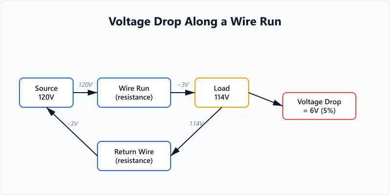
- Apply the formula. For single-phase circuits: Voltage Drop = 2 x I x L x R / 1,000. The factor of 2 accounts for the round-trip distance — current flows out on one conductor and returns on the other. For three-phase circuits, replace 2 with 1.732 (the square root of 3).
- Calculate the percentage. Divide the voltage drop by the source voltage and multiply by 100. A 6V drop on a 120V circuit is 5.0%. A 6V drop on a 12V circuit is 50% — a critical failure.
- Compare against limits. The NEC recommends no more than 3% drop on a branch circuit and 5% total (feeder plus branch). These are informational recommendations, not mandatory code requirements, but exceeding them leads to real operational problems. For sensitive electronics and LED lighting, aim for 2% or less on the branch circuit.
Wire Resistance by AWG Gauge
This table shows the resistance of solid copper and aluminum conductors per 1,000 feet, along with the maximum current each wire safely carries at 75°C insulation rating.
| AWG | Copper (ohms/1000ft) | Aluminum (ohms/1000ft) | Copper Ampacity (75°C) |
|---|---|---|---|
| 14 | 3.14 | 5.17 | 15A |
| 12 | 1.98 | 3.25 | 20A |
| 10 | 1.24 | 2.04 | 30A |
| 8 | 0.778 | 1.28 | 40A |
| 6 | 0.491 | 0.808 | 55A |
| 4 | 0.308 | 0.508 | 70A |
| 2 | 0.194 | 0.319 | 95A |
| 1/0 | 0.122 | 0.201 | 125A |
| 2/0 | 0.0967 | 0.159 | 145A |
The key pattern: each step down in gauge (larger wire) roughly cuts resistance by 37%. Going from 12 AWG to 10 AWG cuts resistance from 1.98 to 1.24 ohms/1000ft — a 37% reduction that proportionally reduces voltage drop. If you are borderline on voltage drop, jumping one wire size is often the simplest fix. For the relationship between wire gauge, current, and wattage, the HP-to-watts guide covers how motor power ratings translate to the amps that drive voltage drop calculations.
Worked Example: Wiring a Detached Shed
You are running a 20A, 120V circuit to a workshop shed that is 150 feet from your main panel. You plan to use 12 AWG copper wire (the standard for a 20A branch circuit).
Voltage drop: 2 x 20A x 150ft x 1.98 / 1,000 = 11.9V. That is 9.9% of 120V — nearly double the NEC 5% recommendation. Your tools will underperform and motors may overheat.
Upgrade to 10 AWG: 2 x 20A x 150ft x 1.24 / 1,000 = 7.4V = 6.2%. Better, but still above 5%.
Upgrade to 8 AWG: 2 x 20A x 150ft x 0.778 / 1,000 = 4.7V = 3.9%. This meets the NEC recommendation. Yes, 8 AWG on a 20A circuit is larger than required by ampacity tables, but voltage drop on long runs demands it. The extra wire cost is the price of a proper installation. Use the amps draw calculator to quickly check the current for any combination of load and voltage.
This is a common real-world scenario. Many electricians have seen sheds, barns, and outbuildings wired with the minimum code-required wire gauge that meets ampacity but fails the voltage drop recommendation because no one checked the distance. Motor loads make the problem worse because full-load amps draw 3-10x more current than lighting or receptacle loads, amplifying the drop.
Copper vs. Aluminum: When Each Makes Sense
Aluminum wire has about 61% of the conductivity of copper. To carry the same current with acceptable voltage drop, aluminum must be 1-2 AWG sizes larger than copper. A circuit that needs 6 AWG copper requires 4 AWG aluminum.
| Factor | Copper | Aluminum |
|---|---|---|
| Resistance (per ft) | Lower | ~64% higher |
| Weight (per ft) | Heavier | ~70% lighter |
| Cost (per ft) | Higher | ~40-60% cheaper |
| Typical use | Branch circuits, short runs | Service entrance, feeders, long runs |
| Connection concerns | Minimal | Requires anti-oxidant compound, rated connectors |
Aluminum is standard for service entrance conductors and large feeder runs where the weight and cost savings are substantial. For the 150-foot shed run above, 6 AWG aluminum achieves similar voltage drop to 8 AWG copper at roughly 50% of the material cost — but requires AL-rated connectors at every termination point. Many electricians prefer copper for branch circuits and residential work because the connections are simpler and more forgiving.
For 12V and 24V DC systems (solar, battery, automotive), copper is nearly universal. The wire sizes needed for low-voltage high-current runs are already large, and aluminum's additional size increase makes routing and termination impractical in tight spaces. If you are sizing cable between a battery and inverter, our inverter cable size calculator handles the low-voltage sizing math where voltage drop is most critical.
Voltage Drop in Solar and Battery Installations
Low-voltage DC wiring is where voltage drop causes the most trouble. A 48V battery bank feeding a 3,000W inverter draws 62.5 amps at full load. Over a 10-foot cable run in 4 AWG copper (0.308 ohms/1000ft), the drop is 2 x 62.5 x 10 x 0.308 / 1,000 = 0.39V — less than 1% and perfectly acceptable.
But the same system at 12V draws 250 amps, and even 2/0 copper over 10 feet drops 2 x 250 x 10 x 0.0967 / 1,000 = 0.48V — still under 5%, but the cable costs several times more. The Copper Development Association publishes detailed resistance and ampacity data that engineers use for these calculations.
This is one reason most off-grid solar installations use 24V or 48V battery banks: higher voltage means lower current, thinner wire, and less voltage drop for the same power delivery. If you are planning cable runs between batteries, charge controllers, and inverters, our inverter cable sizing guide covers the full process including safety derating and temperature correction.
Frequently Asked Questions
Written and maintained by Dan Dadovic, Commercial Director at Ezoic Inc. & PhD Candidate in Information Sciences. He works professionally as Commercial Director at Ezoic Inc., leading revenue strategy across digital publishing.
Disclaimer: Calculator results are estimates based on theoretical formulas. Actual performance varies with temperature, battery age, load patterns, and equipment condition. For critical electrical work, consult a licensed electrician.
Editorial review by Doc. dr. sc. Danijel Jerković-Štil, Assistant Professor, FERIT Osijek.