How to Calculate Voltage Drop Step by Step
- Identify the wire gauge. Check the cable markings or your plan specs. The gauge determines the wire's resistance per foot: thicker wire (lower AWG number) has less resistance. If you haven't chosen a gauge yet, start with the minimum required by NEC ampacity tables and check if the drop is acceptable.
- Measure the one-way run distance. This is the physical distance from the power source (panel, battery, charge controller) to the load. The calculator doubles it internally to account for the return path, since current flows through both conductors.
- Determine the load current. Use the actual expected current draw, not the breaker rating. A 20A breaker circuit may only carry 12A in practice. For motor loads, use the running amps from the nameplate, not the starting surge. If you need to convert watts to amps first, our amps draw calculator handles that conversion. For motors rated in horsepower, convert to watts first with the HP to watts calculator.
- Check the result against NEC recommendations. For branch circuits, keep voltage drop under 3%. For the combined feeder-plus-branch path, stay under 5% total. If the drop exceeds your target, either increase the wire gauge (lower AWG number = thicker wire) or reduce the distance.
- Consider temperature derating. Copper resistance rises about 4% for every 10°C above 20°C. Wire running through a hot attic in summer operates well above standard temperature, so add a safety margin by going one gauge larger than the calculator suggests.
Wire Resistance by Gauge (Ohms per 1,000 Feet)
| AWG | Copper (Ω/1000 ft) | Aluminum (Ω/1000 ft) | Typical Max Amps (75°C) |
|---|---|---|---|
| 14 | 3.14 | 5.17 | 15 |
| 12 | 1.98 | 3.25 | 20 |
| 10 | 1.24 | 2.04 | 30 |
| 8 | 0.778 | 1.28 | 40 |
| 6 | 0.491 | 0.808 | 55 |
| 4 | 0.308 | 0.508 | 70 |
| 3 | 0.245 | 0.403 | 85 |
| 2 | 0.194 | 0.319 | 95 |
| 1 | 0.154 | 0.253 | 110 |
| 1/0 | 0.122 | 0.201 | 125 |
| 2/0 | 0.0967 | 0.159 | 145 |
| 3/0 | 0.0766 | 0.126 | 165 |
| 4/0 | 0.0608 | 0.100 | 195 |
Values are DC resistance at 25°C from NEC Chapter 9 Table 8. AC resistance is slightly higher due to skin effect, but the difference is negligible for wire sizes 4/0 and smaller at 60 Hz. Aluminum resistance is approximately 1.6x that of copper for the same gauge, which is why aluminum installations typically use wire two sizes larger than copper for equivalent performance.
NEC Voltage Drop Recommendations and Why They Matter
The NEC Article 210.19(A) Informational Note No. 4 recommends a maximum 3% voltage drop on branch circuits and 5% total for the combined feeder and branch circuit path. These are recommendations, not hard code requirements, but they exist because excessive voltage drop causes real problems.
A 120V circuit with 5% drop delivers only 114V at the outlet. Most electronics handle that fine, but motors are less forgiving. An induction motor running at reduced voltage draws proportionally more current to maintain torque. That extra current generates heat in the windings, accelerating insulation breakdown and shortening the motor's life. A well pump, compressor, or HVAC blower running on chronically low voltage may fail years before its expected service life. Starting these motors already draws 5-8 times the running current, and low voltage makes the inrush even worse.
Low-voltage DC systems face the challenge at a different scale. A 12V solar circuit with 3% drop loses only 0.36V, but that fraction represents charging current the battery never receives. Over a full day of solar production, a 3% wiring loss on a 1,000W array wastes 30W continuously, roughly 150-180 Wh per day. Over a year, that is 55-65 kWh of energy turned to heat in the wires instead of stored in batteries.
Sizing wire correctly is not just a safety measure: it is an efficiency investment that pays for itself. For long solar wire runs, our wire distance calculator recommends the minimum gauge to meet your drop target.
Worked Examples
120V Kitchen Circuit Voltage Drop Check
Context
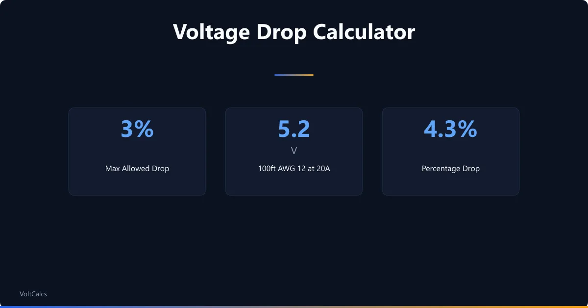
You are wiring a kitchen remodel with a dedicated 20A circuit for countertop outlets. The panel is 75 feet from the farthest outlet. You plan to use 12 AWG copper (standard for 20A circuits). Does the voltage drop stay under 3%?
Calculation
Wire resistance: 12 AWG copper = 1.98 Ω per 1,000 ft
Round-trip distance: 75 ft x 2 = 150 ft
Total resistance: (1.98 / 1,000) x 150 = 0.297 Ω
Voltage drop: 20 A x 0.297 Ω = 5.94 V
Drop percentage: 5.94 / 120 = 4.95%
Interpretation
At 4.95%, this circuit nearly hits the 5% total limit with the branch circuit alone — leaving zero margin for feeder drop. The outlets at the far end would receive only 114V under full load. Appliances like toasters and microwaves that draw close to 20A would underperform noticeably.
Takeaway
Upgrade to 10 AWG copper. At 1.24 Ω/1,000 ft, the drop falls to 3.72V (3.1%) — within the 3% branch circuit recommendation with minimal margin. If your loads typically draw less than 15A, 12 AWG is technically adequate, but the upgrade costs only $30-40 more in wire. To add up all loads on the circuit and see the total draw, use our electrical load calculator.
12V Solar Panel Run to Charge Controller
Context
You have a pair of 200W solar panels mounted 30 feet from your charge controller. The panels produce up to 30A at 12V nominal (Vmp ~18V, Imp ~11A per panel, wired in parallel). You are using 10 AWG copper wire.
Calculation
Wire resistance: 10 AWG copper = 1.24 Ω per 1,000 ft
Round-trip distance: 30 ft x 2 = 60 ft
Total resistance: (1.24 / 1,000) x 60 = 0.0744 Ω
Voltage drop at 30A: 30 x 0.0744 = 2.23 V
Drop percentage at 12V nominal: 2.23 / 12 = 18.6%
Drop percentage at Vmp 18V: 2.23 / 18 = 12.4%
Interpretation
Even at the panels' maximum power voltage (18V), a 12.4% drop is severe. At 12V nominal, 18.6% drop means the charge controller receives only 9.77V — too low to charge a 12V battery. This is a common mistake with low-voltage solar installations over even moderate distances.
Takeaway
Wire the panels in series for 24V (or use a higher voltage configuration) and use an MPPT charge controller. At 24V and 15A (same power, half the current), the drop on 10 AWG falls to a manageable 4.7%. To estimate your panels' actual daily output after accounting for losses, use our solar panel output calculator.
Frequently Asked Questions
Glossary
Circular Mils
A unit of wire cross-sectional area equal to the area of a circle with a diameter of one mil (0.001 inch). Larger circular mil values mean thicker wire with lower resistance. The AWG system is derived from circular mil measurements — 4/0 AWG has 211,600 circular mils while 14 AWG has only 4,110.
Resistivity
A material's inherent resistance to electrical current flow, measured in ohm-circular mils per foot. Copper has a resistivity of 10.75 Ω·cmil/ft at 20°C; aluminum is 17.7 Ω·cmil/ft — about 64% more resistive. Resistivity is a fixed property of the metal; resistance depends on resistivity plus the wire's length and cross-section.
Branch Circuit
The portion of a wiring system between the final overcurrent device (breaker or fuse) and the outlets or equipment it serves. NEC recommends no more than 3% voltage drop on a branch circuit. A typical 15A or 20A residential circuit running from the panel to a room's outlets is a branch circuit.
Designing a solar battery bank and need to size the wire runs between panels, charge controller, and batteries? Our solar battery bank size calculator helps you plan the full system.
Related calculators
Wire Distance Calculator
Calculate voltage drop and recommended wire gauge for any distance. Enter amps, distance, voltage, and target drop percentage.
Electrical
Amps Draw Calculator
Calculate current draw in amps from watts and volts for any device. Supports single-phase and three-phase loads with power factor adjustment.
Electrical
Inverter Cable Size Calculator
Find the right cable gauge for your battery-to-inverter connection. Enter inverter watts, voltage, and distance for safe wire sizing.
Electrical
Motor FLA Calculator
Calculate motor full load amps for single-phase and three-phase motors. Enter HP, voltage, efficiency, and power factor for instant FLA results.
Electrical
Voltage drop is one of the most overlooked factors in electrical installations. It does not trip breakers or blow fuses — it quietly wastes energy and degrades equipment performance over years. Checking the drop before pulling wire takes 30 seconds with this calculator and can save hundreds of dollars in wasted energy and premature equipment failure. For any permanent wiring at permit-required voltages, have a licensed electrician verify your wire gauge and connections. These results are theoretical estimates based on standard resistivity values at 25°C — actual performance varies with temperature, connection quality, and conductor condition. Our voltage drop guide explains the formula, walks through a shed-wiring example, and compares copper vs aluminum conductors.
More Electrical calculators
Browse all electrical calculators — Motor FLA, wire sizing, voltage drop, load calculations, and transformer fusing based on NEC standards.
Last updated:
Written and maintained by Dan Dadovic, Commercial Director at Ezoic Inc. & PhD Candidate in Information Sciences. He works professionally as Commercial Director at Ezoic Inc., leading revenue strategy across digital publishing.
Disclaimer: Calculator results are estimates based on theoretical formulas. Actual performance varies with temperature, battery age, load patterns, and equipment condition. For critical electrical work, consult a licensed electrician.
Editorial review by Doc. dr. sc. Danijel Jerković-Štil, Assistant Professor, FERIT Osijek.