
kVA vs kW: Apparent Power and True Power Explained
A transformer rated at 10 kVA does not necessarily deliver 10 kW of usable power. The "kVA" rating is apparent power: the total power flowing through the circuit, including both the useful component (real power, measured in kW) and the wasted back-and-forth component (reactive power, measured in kVAR).
The relationship is straightforward: kW = kVA x Power Factor. A 10 kVA transformer serving a load with 0.85 power factor delivers 8.5 kW of real power. The remaining 1.5 kVA is reactive power. It oscillates between the source and the inductive load (usually motors or fluorescent ballasts) without doing useful work, but it still creates current in the wires.
This distinction matters because wires and breakers carry amps, and amps come from kVA, not kW. A 10 kVA load at 240V single-phase draws 41.7A regardless of the power factor. The power factor determines how much of that current does useful work, but all of it flows through your conductors and generates heat. Size your wire and breaker for the full kVA-based current, not the reduced kW figure.
Purely resistive loads like space heaters and incandescent lights have a power factor of 1.0, so kVA equals kW. But most real-world loads include motors, transformers, or electronic power supplies that pull the power factor below 1.0. Our amps draw calculator handles the simpler watts-to-amps conversion for resistive loads where power factor is not a concern.
Using kVA-to-Amps Results for Wire Sizing
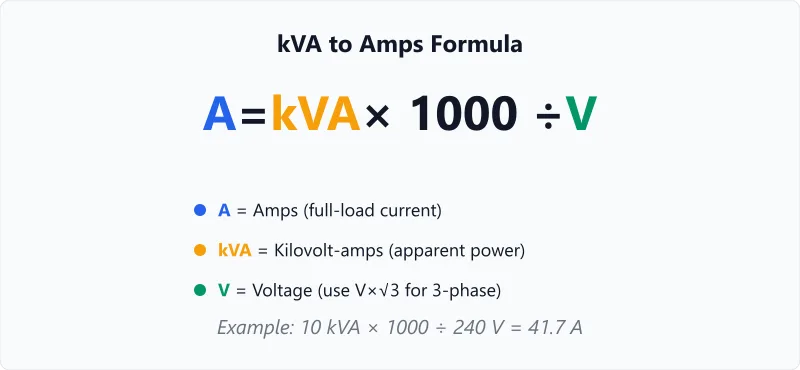
- Get the full load amps from this calculator. For single-phase: Amps = kVA x 1000 / Voltage. For three-phase: Amps = kVA x 1000 / (Voltage x 1.732). Enter your values above and read the current result directly.
- Apply the NEC continuous load multiplier if applicable. Loads expected to run for 3+ hours continuously (lighting, HVAC, commercial kitchen equipment) must have conductors rated at 125% of the calculated current per NEC 210.20. A 41.7A continuous load requires conductors rated for 52.1A.
- Select the wire gauge from NEC ampacity tables. Use NEC Table 310.16 for conductors in raceway or cable. The gauge must handle the multiplied current at the applicable temperature rating (60°C, 75°C, or 90°C depending on the conductor insulation and terminal ratings).
- Check voltage drop on the run. Long feeder runs from transformer to panel can accumulate noticeable voltage drop. After selecting the gauge for ampacity, verify the drop stays under 3% using our wire distance calculator. Upgrade the gauge if needed.
- Size the overcurrent protection. Transformer primary and secondary protection follows NEC Article 450. The fuse or breaker size depends on the transformer kVA, voltage, and whether you are protecting the primary or secondary side. Our transformer fusing calculator handles this directly, and our guide to sizing transformer fuses explains how each percentage is chosen.
Common Transformer Sizes and Full Load Amps
| kVA Rating | 120V 1Ø Amps | 240V 1Ø Amps | 208V 3Ø Amps | 480V 3Ø Amps | Typical Use |
|---|---|---|---|---|---|
| 5 | 41.7 | 20.8 | 13.9 | 6.0 | Small commercial space, branch panel |
| 10 | 83.3 | 41.7 | 27.8 | 12.0 | Residential service, small shop |
| 15 | 125.0 | 62.5 | 41.6 | 18.0 | Multi-unit residential, office suite |
| 25 | 208.3 | 104.2 | 69.4 | 30.1 | Small commercial building |
| 50 | — | 208.3 | 138.8 | 60.1 | Medium commercial, light industrial |
| 75 | — | 312.5 | 208.2 | 90.2 | Large commercial panel |
| 100 | — | 416.7 | 277.6 | 120.3 | Industrial facility section |
| 150 | — | 625.0 | 416.4 | 180.4 | Large industrial, data center |
| 300 | — | — | 832.8 | 360.8 | Heavy industrial main service |
| 500 | — | — | 1,388 | 601.4 | Utility substation, campus main |
These are maximum full load amps at unity power factor (PF = 1.0). Actual current at the typical 0.80-0.90 power factor of most facilities will be the same — kVA determines amps regardless of PF. The real power (kW) delivered to the load will be less. Dashes indicate combinations that are impractical or not standard for that transformer size.
Worked Examples
Sizing Wiring for a 10 kVA Single-Phase Transformer
Context
A 10 kVA single-phase transformer supplies a small commercial space at 240V. The load mix includes lighting, HVAC, and a few small motors with an estimated power factor of 0.85. You need to size the secondary conductors and breaker.
Calculation
Full load amps: (10 kVA x 1,000) / 240 V = 41.7 A
True power: 10 kVA x 0.85 PF = 8.5 kW
Reactive power: √(10² - 8.5²) = √(100 - 72.25) = √27.75 = 5.27 kVAR
For continuous loads, NEC requires conductors rated at 125%: 41.7 x 1.25 = 52.1 A minimum
Interpretation
The secondary conductors must handle at least 52.1A (continuous load rating). That puts you in 6 AWG copper territory per NEC Table 310.16 at 75°C. A 60A breaker on the secondary provides proper overcurrent protection with room for the load to grow slightly.
Takeaway
The 41.7A flowing through the wires exists regardless of the 0.85 power factor — that PF only reduces the real power (kW) the load uses, not the current the wires carry. For the wire run from transformer to panel, use our voltage drop calculator to verify the conductors are heavy enough for the distance.
Three-Phase Motor Starter Sizing
Context
A 25 kVA three-phase motor load runs at 480V with a measured power factor of 0.80. You need to determine the line current for wire sizing and starter selection.
Calculation
Full load amps: (25 kVA x 1,000) / (480 V x 1.732) = 25,000 / 831.4 = 30.1 A per line
True power: 25 kVA x 0.80 PF = 20.0 kW
Reactive power: √(25² - 20²) = √(625 - 400) = √225 = 15.0 kVAR
Interpretation
Each line conductor carries 30.1A. At 480V three-phase, this is modest current — 10 AWG copper is adequate for ampacity. The 15 kVAR of reactive power is substantial (60% of the real power), indicating the motor is operating at a relatively poor power factor. Power factor correction capacitors could reduce the line current.
Takeaway
A NEMA Size 1 starter handles up to 27A at 480V, so this motor needs a NEMA Size 2 (up to 45A). The motor FLA from the nameplate may differ from this kVA-based calculation — always verify with nameplate data. Our motor FLA calculator computes FLA directly from the motor's HP rating for a more precise result.
Frequently Asked Questions
Glossary
Apparent Power (kVA)
The total power flowing in an AC circuit, combining both real power (kW) and reactive power (kVAR). Measured in kilovolt-amperes. This is what transformers, conductors, and breakers must be rated for because it determines the actual current flowing through the circuit regardless of power factor.
True Power (kW)
The portion of apparent power that performs useful work — running motors, generating heat, powering electronics. Measured in kilowatts. True power equals apparent power multiplied by the power factor: kW = kVA x PF. This is what your electricity meter measures and what you pay for.
Reactive Power (kVAR)
The portion of apparent power that oscillates between the source and inductive or capacitive loads without doing useful work. Measured in kilovolt-amperes reactive. Motors, transformers, and fluorescent ballasts create reactive power. High reactive power means low power factor, which wastes conductor capacity and can incur utility surcharges.
Planning a battery backup for transformer-fed equipment? Our UPS battery backup calculator estimates how long your battery bank sustains the load during an outage.
Related calculators
Fusing Transformer Calculator
Calculate primary and secondary fuse sizes for power transformers. Enter kVA, primary and secondary voltages, and NEC multipliers.
Electrical
Amps Draw Calculator
Calculate current draw in amps from watts and volts for any device. Supports single-phase and three-phase loads with power factor adjustment.
Electrical
HP to Watts Calculator
Convert horsepower to watts and watts to HP instantly. Supports mechanical, electrical, and metric horsepower with precise conversion factors.
Electrical
Generator Sizing Calculator
Find the right generator size for your loads. Enter running watts, motor surge, and power factor for an instant recommendation with safety margin.
Electrical
Transformer kVA ratings exist because transformers do not care about power factor. They must handle the full apparent power regardless of how much real work the load does. A transformer supplying a motor with 0.70 power factor carries 43% more current than one supplying a resistive heater of the same kW. If the load includes battery charging for a solar battery bank, size the transformer for the charger's full kVA rating including any power factor correction. Both scenarios are within the transformer's design, but the low-PF load requires heavier wiring and larger breakers. When sizing electrical infrastructure, always work from kVA and amps (not kW) to ensure your conductors and protection can handle the actual current flowing through them. For a deeper explanation of the power triangle and when this distinction matters, read our kVA vs kW guide.
More Electrical calculators
Browse all electrical calculators — Motor FLA, wire sizing, voltage drop, load calculations, and transformer fusing based on NEC standards.
Last updated:
Written and maintained by Dan Dadovic, Commercial Director at Ezoic Inc. & PhD Candidate in Information Sciences. He works professionally as Commercial Director at Ezoic Inc., leading revenue strategy across digital publishing.
Disclaimer: Calculator results are estimates based on theoretical formulas. Actual performance varies with temperature, battery age, load patterns, and equipment condition. For critical electrical work, consult a licensed electrician.
Editorial review by Doc. dr. sc. Danijel Jerković-Štil, Assistant Professor, FERIT Osijek.