Why Transformer Fusing Exists
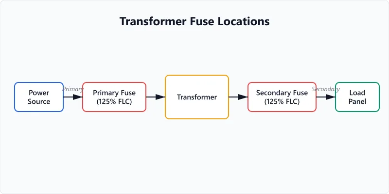
Transformers need overcurrent protection on both sides, but for different reasons. The primary fuse protects the transformer itself from short circuits and overloads on the secondary side. The secondary fuse protects the downstream wiring and loads.
Without proper fusing, a short circuit on the secondary side would cause the transformer to draw excessive current from the primary supply. The transformer's windings overheat, insulation breaks down, and at worst the transformer fails catastrophically — with smoke, fire, or oil rupture on larger units.
The primary fuse also limits the available fault current downstream. A utility service might deliver 10,000+ amps of short circuit current. Without a properly sized primary fuse, that entire fault current flows through the transformer into whatever caused the short.
NEC Article 450 governs transformer protection. The rules differ based on transformer size, impedance, and whether overcurrent protection exists on both sides. Getting this right matters for both safety and code compliance — an inspector will check fuse sizing on any permitted installation.
Step-by-Step Fuse Sizing for Transformers
- Calculate the full load current (FLC) on each side. FLC = (kVA x 1000) / Voltage. A 15 kVA transformer at 480V primary draws 31.25A. The same transformer at 120V secondary delivers 125A. The current ratio is the inverse of the voltage ratio: step down the voltage, step up the current.
- Apply the primary protection multiplier. NEC 450.3(B) allows the primary fuse to be up to 125% of primary FLC. So 31.25A x 1.25 = 39.06A. Round up to the next standard fuse size: 40A. If 125% does not correspond to a standard fuse size, NEC allows the next size up (up to 150% for primary-only protection).
- Apply the secondary protection multiplier. When both primary and secondary protection are provided, NEC allows the secondary fuse up to 125% of secondary FLC. When the secondary is 9A or more, NEC allows 125%: 125A x 1.25 = 156.25A, rounding to a 175A fuse. The 167% figure sometimes seen is the primary-only multiplier for 2-9A primary current (NEC 450.3(B)), not a secondary value.
- Select standard fuse sizes. Fuses come in standard ampere ratings: 15, 20, 25, 30, 35, 40, 45, 50, 60, 70, 80, 90, 100, 110, 125, 150, 175, 200, 225, 250, 300, 350, 400, 450, 500, 600. Your calculated value rounds up to the nearest standard size.
- Verify coordination. The primary fuse must clear (blow) before the secondary fuse on a downstream fault. If they do not coordinate, a small secondary fault can trip the primary, taking down everything on that transformer rather than just the faulted circuit.
NEC 450.3(B) Protection Multipliers Reference
| Protection Configuration | Primary (% of FLC) | Secondary (% of FLC) | NEC Section |
|---|---|---|---|
| Primary only, primary 9A or more | 125% (next size up) | N/A | 450.3(B) |
| Primary only, primary 2-9A | 167% | N/A | 450.3(B) |
| Primary only, primary under 2A | 300% | N/A | 450.3(B) |
| Primary and secondary protected | 250% | 125% | 450.3(B) |
| Over 1000V, supervised | 300% | 250% | 450.3(A) |
This calculator defaults to 125% primary and 125% secondary, the common primary-and-secondary-protected configuration for small to medium dry-type transformers. Adjust the multipliers for your case: 167% and 300% are primary-only values for low primary currents (2-9A and under 2A), not secondary values. The over-1000V supervised rules (NEC 450.3(A)) apply to industrial facilities with qualified personnel; installations at 1000V or less use 450.3(B).
For critical electrical installations, always have a licensed electrician verify the fuse sizing against the specific NEC edition adopted by your jurisdiction. Local amendments may modify these values.
Worked Examples
Fusing a 45 kVA Lighting Transformer
Context
A commercial building has a 45 kVA 3-phase dry-type transformer stepping 480V down to 208V for lighting panels. You need to select primary and secondary fuses per NEC 450.3.
Calculation
Primary FLC (3-phase): 45,000 / (480 × √3) = 45,000 / 831.4 = 54.1 A
Primary fuse (125% per NEC): 54.1 × 1.25 = 67.6 A → next standard size: 70 A
Secondary FLC (3-phase): 45,000 / (208 × √3) = 45,000 / 360.2 = 124.9 A
Secondary fuse (125%): 124.9 × 1.25 = 156.2 A → next standard size: 175 A
Interpretation
The primary side gets a 70A fuse and the secondary a 175A fuse. The 3-phase formula divides by √3 (≈1.732), which produces lower per-line currents than the single-phase formula for the same kVA — because three conductors share the load.
Takeaway
The loads downstream of this transformer still need individual breakers. Use our amps draw calculator to verify each lighting circuit's current draw before selecting branch breakers. For the wire run between the transformer and lighting panel, check the voltage drop to confirm the conductors are heavy enough for the distance.
Protecting a Medium-Voltage Transformer Primary
Context
A 75 kVA 3-phase transformer has a 4,160V primary (medium voltage) and 480V secondary. NEC allows up to 300% primary fusing for transformers over 1000V per 450.3(A).
Calculation
Primary FLC (3-phase): 75,000 / (4,160 × √3) = 75,000 / 7,205.1 = 10.4 A
Primary fuse (300%): 10.4 × 3.0 = 31.2 A → next standard size: 30 A
Secondary FLC (3-phase): 75,000 / (480 × √3) = 75,000 / 831.4 = 90.2 A
Secondary fuse (125%): 90.2 × 1.25 = 112.8 A → next standard size: 125 A
Interpretation
Medium-voltage 3-phase primaries draw very low per-line current. The 300% multiplier compensates for magnetizing inrush — without it, fuses would nuisance-blow every time the transformer is energized.
Takeaway
Transformer protection gets complex at higher voltages. For the motors downstream, calculate their individual FLA with our motor FLA calculator to size each motor branch circuit correctly.
Frequently Asked Questions
Glossary
Full Load Current
The current a transformer draws at its rated kVA and voltage. FLC on the primary and secondary sides differ because of the voltage ratio — lower voltage means higher current for the same power.
NEC Fuse Multiplier
NEC Article 450.3 specifies maximum fuse sizes as percentages of the transformer FLC. The multiplier depends on voltage level, transformer type, and whether primary protection alone is used or both primary and secondary.
Inrush Current
The surge of magnetizing current a transformer draws when first energized. Typically 10-15 times the FLC for a fraction of a second. Fuses must be sized large enough to ride through this inrush without blowing.
Planning a battery backup for transformer-fed equipment? Our battery runtime calculator estimates how long your UPS would sustain the load during an outage.
Related calculators
kVA to Amps Calculator
Convert kVA to amps for single-phase and three-phase systems. Enter kVA, voltage, and power factor for instant current and true power results.
Electrical
Locked Rotor Amps (LRA) Calculator
Calculate motor locked rotor amps (LRA) for starting current estimation. Enter FLA and multiplier based on NEMA code letter.
Electrical
Amps Draw Calculator
Calculate current draw in amps from watts and volts for any device. Supports single-phase and three-phase loads with power factor adjustment.
Electrical
Motor FLA Calculator
Calculate motor full load amps for single-phase and three-phase motors. Enter HP, voltage, efficiency, and power factor for instant FLA results.
Electrical
Transformer fuse sizing is a code-compliance requirement, not a suggestion. If the transformer feeds a solar installation or UPS battery backup system, the fusing still follows the same NEC rules. Oversized fuses fail to protect the transformer. Undersized fuses blow under normal load. The values this calculator produces are starting points — verify against the specific NEC edition your jurisdiction enforces and the transformer manufacturer's recommended protection. For any permitted installation, have a licensed electrician specify the final fuse sizes. These results are estimates based on the kVA and voltage values you enter.
More Electrical calculators
Browse all electrical calculators — Motor FLA, wire sizing, voltage drop, load calculations, and transformer fusing based on NEC standards.
Last updated:
Written and maintained by Dan Dadovic, Commercial Director at Ezoic Inc. & PhD Candidate in Information Sciences. He works professionally as Commercial Director at Ezoic Inc., leading revenue strategy across digital publishing.
Disclaimer: Calculator results are estimates based on theoretical formulas. Actual performance varies with temperature, battery age, load patterns, and equipment condition. For critical electrical work, consult a licensed electrician.
Editorial review by Doc. dr. sc. Danijel Jerković-Štil, Assistant Professor, FERIT Osijek.