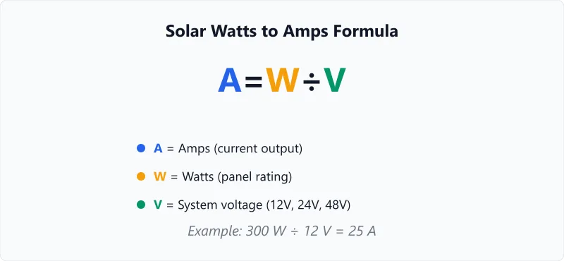
The Formula Behind Watts to Amps
The conversion is straightforward: Amps = Watts / Volts. This is a rearrangement of the basic power equation P = V x I, where P is power in watts, V is voltage, and I is current in amps.
The critical detail for solar is which voltage you use. A 400W panel might have a Vmp (voltage at maximum power point) of 37V, but your battery bank is 12V. The amps flowing from the panel are 400 / 37 = 10.8A. The amps flowing into a 12V battery through an MPPT controller are 400 / 12 = 33.3A (minus controller losses).
This distinction matters because the wire between panels and controller carries the lower panel-side current, while the wire between controller and battery carries the higher battery-side current. Size each wire run for the current it actually carries, not a single number for the whole system.
Quick Reference: Common Solar Panel Amps
| Panel Wattage | At 12V Battery | At 24V Battery | At 48V Battery | At Vmp (~37V) |
|---|---|---|---|---|
| 100W | 8.3A | 4.2A | 2.1A | 2.7A |
| 200W | 16.7A | 8.3A | 4.2A | 5.4A |
| 300W | 25.0A | 12.5A | 6.3A | 8.1A |
| 400W | 33.3A | 16.7A | 8.3A | 10.8A |
| 600W | 50.0A | 25.0A | 12.5A | 16.2A |
| 1000W | 83.3A | 41.7A | 20.8A | 27.0A |
Battery-side amps assume MPPT controller with 100% efficiency. Real-world current is 5-15% lower due to controller and wiring losses.
What to Do With Your Amps Number
- Size your charge controller. The controller must handle the total battery-side current. If your array produces 33A at battery voltage, pick a controller rated for at least 40A (add a 20% margin for voltage spikes and temperature derating).
- Pick the right wire gauge. Use the battery-side amps to select wire thickness. For 33A over a 3-metre run, 6 AWG (13.3mm²) copper keeps voltage drop under 3%. Undersized wire wastes energy as heat and creates a fire risk. Verify your choice with the voltage drop calculator.
- Select fuses and breakers. Place a fuse on the positive wire between controller and battery, rated 25% above your expected maximum current. For 33A, use a 40A fuse. The fuse protects against short circuits that could pull hundreds of amps from the battery through the wiring.
Worked Examples
Selecting a Charge Controller for a 3-Panel 12V System
Context
Calculation
Total array wattage = 3 × 400W = 1,200W
Battery-side amps = 1,200W / 12V = 100A
With 20% safety margin: 100 × 1.2 = 120A
Interpretation
The battery-side current is 100A, which is very high for a 12V system. A single 100A MPPT controller would run at maximum capacity with no headroom. A 120A+ controller, or two 60A controllers on separate sub-arrays, would be safer and more efficient.
Takeaway
High amps at low voltage drive up hardware costs. This is a strong argument for switching to a 24V system, which halves the current to 50A. Use the inverter cable size calculator to see the wire gauge difference between 100A at 12V and 50A at 24V.
Fuse Sizing for a Rooftop Panel-to-Controller Run
Context
Calculation
Panel-side amps = 800W / 74V = 10.8A
Fuse rating = 10.8 × 1.25 = 13.5A → 15A fuse (next standard size)
Interpretation
At 10.8A, the panel-to-controller cable only needs to handle moderate current. A 15A fuse protects the cable. The wire gauge can be much thinner here (10 AWG is fine for typical runs) compared to the battery side, where the same 800W at 12V would demand 67A and 2 AWG cable.
Takeaway
Series wiring raises voltage and drops current on the panel side, which simplifies cable runs. To calculate your full daily energy harvest from this 800W array, use the solar panel output calculator.
Frequently Asked Questions
Glossary
Maximum Power Point
The voltage-current combination at which a solar panel produces its highest wattage output. MPPT controllers continuously adjust to find this optimal point, which shifts with temperature and irradiance throughout the day.
Battery-Side Current
The current flowing between the charge controller and battery bank. Because MPPT controllers step voltage down from panel level to battery level, battery-side current is 2-3x higher than panel-side current for the same power.
Voltage Drop
The loss of voltage along a wire due to the wire's resistance. Longer wire runs and thinner gauges cause more voltage drop. For solar systems, total voltage drop should stay below 3% to avoid measurable energy loss. Our voltage drop guide explains the causes and fixes.
Need to convert your panel output from watts to amp-hours for battery sizing? Our watt-hours to amp-hours calculator handles the conversion.
Related calculators
Solar Panel Output Calculator
Calculate daily and monthly energy output from your solar panels. Enter wattage, sun hours, and panel count for instant results.
Solar
Watt Hours to Amp Hours Calculator
Convert watt-hours to amp-hours at any voltage. Use this to compare batteries rated in different units.
Battery
Solar Panel Calculator
Free solar panel calculator: enter your daily energy use and sun hours to get the panel wattage and number of panels for a home, RV, or off-grid setup.
Solar
Solar Time Calculator
Calculate apparent solar time and solar noon for any location. Enter longitude and date to find when the sun is highest.
Solar
Watts tell you energy. Amps tell you what hardware to buy. Every wire, fuse, breaker, and connector in your solar system is rated in amps — getting this conversion right is the difference between a safe system and a fire waiting to happen. When in doubt, round up to the next standard wire gauge and fuse size. For long cable runs between panels and batteries, the wire distance calculator ensures your gauge prevents excessive voltage drop.
More Solar calculators
Browse all solar calculators — Panel output, battery bank sizing, charge time, and system design for off-grid, RV, and residential setups.
Last updated:
Written and maintained by Dan Dadovic, Commercial Director at Ezoic Inc. & PhD Candidate in Information Sciences. He works professionally as Commercial Director at Ezoic Inc., leading revenue strategy across digital publishing.
Disclaimer: Calculator results are estimates based on theoretical formulas. Actual performance varies with temperature, battery age, load patterns, and equipment condition. For critical electrical work, consult a licensed electrician.
Editorial review by Doc. dr. sc. Damir Topić, Assistant Professor, FERIT Osijek.