How to Size Transformer Fuses With NEC 450.3
Last updated:
8 min read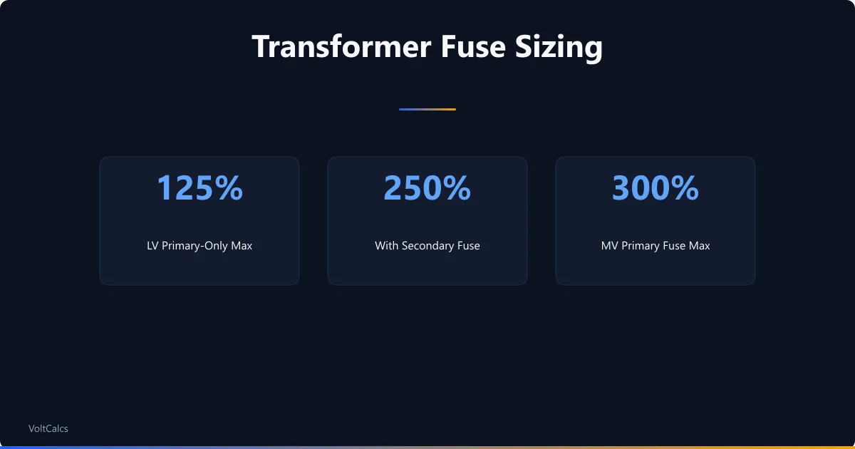
Transformer fuse sizing starts with the full-load current on each side, then applies a maximum percentage set by NEC Table 450.3. For a transformer rated 1,000 V and under, the primary fuse can be up to 125% of full-load current when it is the only protection, rising to 250% when the secondary is separately protected. The result rounds up to the next standard fuse size.
Those percentages are ceilings, not targets. They cap how large a fuse the code allows so the device still protects the transformer, while leaving room to ride through the magnetizing surge a transformer pulls the instant it is energized. This guide works through both 450.3 tables, the four-step method that turns a nameplate into a fuse size, and two examples drawn from questions installers actually ask. To put your own numbers in, the transformer fusing calculator runs the same math — this is the reasoning behind its output. Sizing works from kVA rather than kW because the windings carry apparent power regardless of power factor, which the kVA versus kW guide explains in full.
The NEC 450.3 Tables: Maximum Fuse Percentages
Article 450 splits transformer protection into two tables by voltage class. Table 450.3(B) covers transformers rated 1,000 V and less — the dry-type units behind most commercial and residential work. Table 450.3(A) covers anything over 1,000 V, where medium-voltage inrush forces the percentages much higher. Start with the low-voltage table, since that is where the majority of installations land.
| Protection method | Primary 9 A or more | Primary 2–9 A | Primary under 2 A | Secondary 9 A or more | Secondary under 9 A |
|---|---|---|---|---|---|
| Primary only | 125% | 167% | 300% | Not required | Not required |
| Primary and secondary | 250% | 250% | 250% | 125% | 167% |
The pattern rewards adding secondary protection. With a fuse on the secondary side, the primary fuse can be sized at 250% of full-load current, which buys far more inrush headroom than the 125% allowed when the primary stands alone. Where a calculated value falls between standard fuse ratings, Note 1 to the table permits the next higher standard size — so a 39 A result becomes a 40 A fuse rather than a 35 A that would nuisance-blow under normal load.
The current brackets in the primary-only row matter for small transformers. A primary above 9 A uses 125%; between 2 and 9 A the ceiling rises to 167%; below 2 A it reaches 300%. The reason is proportion — on a tiny primary current, inrush is a far larger multiple of full-load amps, so the code widens the allowance to keep the fuse from blowing on startup. A 2 kVA, 480 V control transformer drawing about 4 A on the primary, for instance, lands in the 167% band rather than 125%.
Above 1,000 V the rules change shape. Now the location of the installation and the transformer's impedance both move the numbers, and the table separates circuit breakers from fuses because the two devices clear faults differently. Percentages reach 600% on a primary breaker — a figure that looks alarming until you remember a medium-voltage transformer's magnetizing inrush can hit ten to fifteen times full-load current for a fraction of a second.
| Location | Protection | Impedance | Primary breaker | Primary fuse | Secondary breaker | Secondary fuse |
|---|---|---|---|---|---|---|
| Any location | Primary + secondary | 6% or less | 600% | 300% | 300% | 250% |
| Any location | Primary + secondary | Over 6% to 10% | 400% | 300% | 250% | 225% |
| Supervised only | Primary only | Any | 300% | 250% | Not required | Not required |
| Supervised only | Primary + secondary | 6% or less | 600% | 300% | 300% | 250% |
| Supervised only | Primary + secondary | Over 6% to 10% | 400% | 300% | 250% | 225% |
Read each row by its location, protection method, and impedance, and the maximum for the primary and secondary device falls out. The any-location rows are the baseline, available everywhere, and require protection on both sides; the supervised-only rows add options reserved for installations with qualified staff who can respond to a fault, including a primary-only choice that needs no secondary device at all. The secondary breaker and fuse columns apply when the secondary is itself over 1,000 V. For the more common step-down case (a secondary rated 1,000 V or less, such as a 4,160 V to 480 V unit), the secondary device instead follows the low-voltage figure: 125% of secondary full-load current in an unsupervised location, or 250% where the location is supervised. These values come straight from NFPA 70 Article 450, and the full grid is displayed cell-for-cell in this NEC 450.3 reference from Electrical Engineering Portal. One edition note worth carrying: the 2014 NEC moved the line between the two tables from 600 V to 1,000 V. The percentages themselves did not change, only the voltage label on the boundary, so older references that read "over 600 volts" still hold the same numbers.
The Four-Step Sizing Method
The tables look dense, but one short routine produces every fuse size in them. Run the steps in order and the correct column falls out on its own.
- Find the full-load current on each side. For a single-phase transformer, full-load amps equals the volt-amp rating divided by the voltage; for three-phase, divide by the voltage times 1.732. The nameplate kVA and the two voltages are all you need. The kVA to amps calculator handles this conversion if you would rather not run it by hand.
- Pick the table and column. Voltage class chooses the table — 1,000 V and under is 450.3(B), over 1,000 V is 450.3(A). Then decide whether the transformer has primary-only protection or protection on both sides, and read the matching row.
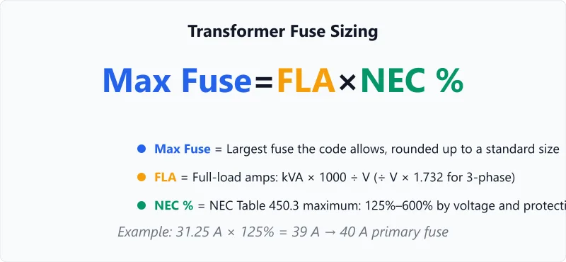
- Multiply the full-load current by the percentage. A 125% cell means full-load amps times 1.25. That product is the largest device the code allows on that side.
- Round up to a standard size. Fuses come in fixed ratings (15, 20, 25, 30, 40, 50, 60, 70, 80, 90, 100, 110, 125, 150, 175, 200 A and up). If the calculated maximum lands between two, Note 1 lets you take the next standard size up rather than down.
Worked Example: A 15 kVA, 480/120 V Transformer
A small single-phase control transformer steps 480 V down to 120 V and carries only a primary fuse. This is the most common arrangement on a shop floor, and it shows the low-voltage table at its simplest.
Primary full-load current is 15,000 ÷ 480 = 31.25 A. With primary-only protection and a current above 9 A, Table 450.3(B) caps the fuse at 125%: 31.25 × 1.25 = 39.1 A. No standard fuse sits at 39 A, so Note 1 allows the next size up — a 40 A primary fuse. On the secondary, the same transformer delivers 15,000 ÷ 120 = 125 A, which is why the downstream conductors and panel run so much heavier than the primary feed.
Add a secondary fuse and the primary ceiling jumps to 250% (78 A, rounding to an 80 A fuse), while the secondary fuse takes the 125% column: 125 × 1.25 = 156 A, rounding to 175 A. Either approach is code-compliant; the choice usually comes down to whether the secondary conductors need their own dedicated protection at the transformer. For the wire run between the transformer and its panel, a quick voltage-drop check confirms the conductors are heavy enough for the distance.
Worked Example: A 7,200 V Primary and the 150% Myth
A frequent search runs along the lines of "15 kVA transformer fuse size, 7,200 V primary, at 150%." The voltage is the tell that something is off. At 7,200 V the transformer sits over 1,000 V, so Table 450.3(A) governs — not the 125% habit people carry over from low-voltage work.
Primary full-load current is only 15,000 ÷ 7,200 = 2.08 A. In an unsupervised location with a transformer impedance of 6% or less, the primary fuse can be sized at 300%: 2.08 × 3.0 = 6.25 A. Hold that fuse down to the 150% the searcher assumed and you land near 3.1 A — small enough that the transformer's magnetizing inrush would blow it on the first energization. The higher percentage is not a loophole; it is the code accounting for a surge a low-voltage rule of thumb never sees. The same physics drives motor inrush sizing, where a breaker is set well above running current to survive the startup spike.
Why the Percentages Change: Voltage, Impedance, and Supervision
Three variables move the numbers in 450.3, and each traces back to a physical reason rather than a bureaucratic one.
Voltage class is the largest lever. A medium-voltage transformer draws a heavier, longer magnetizing inrush than a low-voltage unit, so a tightly sized fuse would trip every time the transformer is switched on. That is why over-1,000 V primaries climb to 300% on a fuse and 600% on a breaker, while a 480 V unit stays near 125%.
Impedance sets how much fault current the transformer will pass. A low-impedance transformer (6% or less) lets through more short-circuit current, so its breaker is allowed a higher setting to coordinate with downstream devices; a higher-impedance unit chokes the fault itself, and the allowed setting drops. The 6% and 10% breakpoints in the table mark those bands.
Supervision reflects who is watching. A supervised location — an industrial plant with qualified staff and maintenance procedures — is trusted to respond to a fault quickly, so the code grants wider primary latitude and, in some rows, drops the requirement for a separate secondary device. A transformer in an unattended spot gets the tighter "any location" rows. If you are also sizing the source feeding such a transformer, the generator sizing calculator builds the same surge headroom into standby power.
Primary vs Secondary: What Each Fuse Protects
The two fuses on a transformer do different jobs, and that is why the code treats them with separate percentages rather than one shared number. The primary fuse guards the transformer itself (its windings, its core, and the supply feeding it) against a sustained overload or an internal fault. The secondary fuse guards the wiring and equipment downstream, where the load actually lives.
The split also explains the 250% allowance. When a secondary device is present to catch downstream overloads, the primary fuse no longer has to do double duty, so the code lets it grow to 250% purely to ride inrush and clear primary-side faults. Take the secondary protection away and that same primary fuse must also sense secondary overloads, which is why the primary-only column tightens back to 125%.
Coordination ties it together. The secondary fuse should clear a downstream fault before the primary fuse reacts, so a fault on one branch drops that branch and not the whole transformer. Getting the two sizes to nest in that order, secondary fast and primary patient, is the difference between a contained trip and a building-wide outage. Where the load is a motor, its starting current shapes the coordination too, and the motor FLA calculator gives the running figure those curves build on.
The percentages in 450.3 are firm code maximums, but maximums is the key word. A designer often picks a smaller fuse for tighter overload and short-circuit protection, and a local inspector or the transformer manufacturer's instructions can require lower still. A fuse sized right at the ceiling protects the transformer and passes inspection, yet it is not automatically the best engineering choice for the equipment behind it. Treat the figures here as the code limit and a design starting point — not a guarantee — and for any permitted installation have a licensed electrician set the final sizes against the NEC edition your jurisdiction enforces.
Frequently Asked Questions
Written and maintained by Dan Dadovic, Commercial Director at Ezoic Inc. & PhD Candidate in Information Sciences. He works professionally as Commercial Director at Ezoic Inc., leading revenue strategy across digital publishing.
Disclaimer: Calculator results are estimates based on theoretical formulas. Actual performance varies with temperature, battery age, load patterns, and equipment condition. For critical electrical work, consult a licensed electrician.
Editorial review by Doc. dr. sc. Danijel Jerković-Štil, Assistant Professor, FERIT Osijek.