Locked Rotor Amps: Why Motors Spike at Startup
Last updated:
8 min read
Locked rotor amps (LRA) is the brief current surge a motor draws the instant it starts, typically 5 to 8 times its running current, while the rotor is still stationary and producing no back-EMF. It lasts a second or two, but it sizes the breaker, generator, and inverter that must survive the start.
Running current sizes your wire and overload relay. The startup surge is a different number with a different job. This guide explains where LRA comes from, how to read it straight off a motor's NEMA code letter, and why it sets the size of nearly everything upstream of the motor except the wire. To turn your own nameplate into a number, run it through the LRA calculator — this guide is the reasoning behind it.
Locked Rotor Amps vs Full Load Amps
A motor has two current ratings that get confused constantly. Full load amps (FLA) is the steady current it draws once it is up to speed and pulling its rated mechanical load. That is the number the National Electrical Code uses to size branch-circuit conductors and the overload relay, the protection that guards the motor itself. Our full-load amps explainer covers that side in depth, and the FLA calculator works it out from horsepower and voltage.
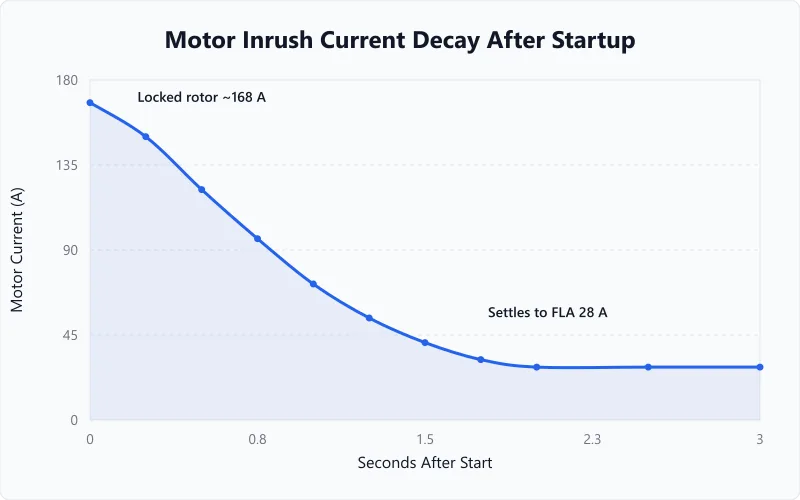
Locked rotor amps is the other number: the spike the same motor pulls in the first moment of starting, before the rotor turns. It runs 5 to 8 times the FLA for a standard induction motor. A motor with a 28 A full-load rating briefly draws around 168 A, then the current falls back toward 28 A as the rotor speeds up. Because that spike is so short, it does not heat the wire, but it can trip a breaker, weld a contactor, or drag a generator's voltage down.
If the comparison sounds familiar, it is the motor version of cold cranking amps. A car battery is rated for the heavy surge needed to crank an engine, not the trickle that runs the radio; the same sizing logic drives our cold cranking amps calculator. A motor's locked rotor amps is its cranking number — the surge the supply has to deliver on demand, separate from the load it carries the rest of the time.
Why a Stopped Motor Pulls So Much Current
When power hits a stopped motor, the rotor is not turning, so it generates no back-EMF, the opposing voltage a spinning rotor normally produces. Without that opposition, the stator windings see almost the full supply voltage across a very low impedance, and they behave nearly like a short circuit. Current rushes in at several times the running value.
As the rotor accelerates, back-EMF builds and the current drops. For most motors the whole event takes 0.5 to 3 seconds; small fractional-horsepower motors are up to speed in well under a second, while large motors driving high-inertia loads like fans or flywheels take longer. The current does not hold at full surge and then snap down, it decays the whole way, as the inrush-decay curve above shows.
The name "locked rotor" describes the worst case: a rotor physically held still. A seized bearing, a jammed pump, or a frozen compressor stops the rotor from ever turning, so back-EMF never builds and the surge never subsides. The motor draws locked rotor amps continuously until the overload relay or breaker opens. A cold motor adds a little to the figure too, since cold windings have slightly lower resistance, so use the higher end of a range when a motor starts cold in an unheated space.
Reading Locked Rotor Amps From the NEMA Code Letter
Most starting-current estimates multiply FLA by a rough factor. There is a more direct route printed right on the nameplate: the NEMA code letter. A single letter from A to V encodes how many kilovolt-amperes per horsepower the motor draws with its rotor locked. NEC Table 430.7(B) assigns each letter a band:
| Code Letter | kVA/HP (Locked Rotor) | Code Letter | kVA/HP (Locked Rotor) |
|---|---|---|---|
| A | 0-3.14 | L | 9.0-9.99 |
| B | 3.15-3.54 | M | 10.0-11.19 |
| C | 3.55-3.99 | N | 11.2-12.49 |
| D | 4.0-4.49 | P | 12.5-13.99 |
| E | 4.5-4.99 | R | 14.0-15.99 |
| F | 5.0-5.59 | S | 16.0-17.99 |
| G | 5.6-6.29 | T | 18.0-19.99 |
| H | 6.3-7.09 | U | 20.0-22.39 |
| J | 7.1-7.99 | V | 22.4 and up |
| K | 8.0-8.99 |
The letters I, O, and Q are skipped to avoid confusion with numbers, leaving 19 in use. Higher letters mean a stiffer start: a Code A motor sips at startup, while a Code R pulls hard. You will also see this table written with rounded, shared boundaries (Code B as 3.15 to 3.55 rather than 3.15 to 3.54, for example); the two forms classify motors identically, so 3.14 is Code A and 3.15 is Code B either way.
To get amps from the letter, take the kVA-per-horsepower figure (use the top of the band for conservative sizing), multiply by the horsepower for locked-rotor kVA, then convert to current:
Three-phase: LRA = (1,000 × locked-rotor kVA) ÷ (Volts × 1.732)
Single-phase: LRA = (1,000 × locked-rotor kVA) ÷ Volts
The advantage over the multiply-by-six shortcut is that you never need a measured FLA; the code letter carries the starting information by itself.
Worked Example: LRA From a Nameplate Code Letter
Take a 25 HP, 460 V, three-phase motor stamped with code letter F. You want the starting current before energizing it, working only from the nameplate.
- Look up the letter. Code F tops out at 5.59 kVA per horsepower in NEC Table 430.7(B). Using the top of the band gives a conservative, worst-case start.
- Find locked-rotor kVA. 25 HP × 5.59 = 139.75 kVA.
- Convert to amps. LRA = (1,000 × 139.75) ÷ (460 × 1.732) = 139,750 ÷ 796.7 ≈ 175 A.
Cross-check it against the running current. The same motor's full-load amps is 34 A, the NEC 430.250 table value, so the start pulls about 175 ÷ 34 ≈ 5.1 times FLA, right in the range the code letter implies. The two methods agree.
Now the protection. NEC 430.52 lets an inverse-time breaker run up to 250% of FLA on a motor branch circuit: 2.5 × 34 = 85 A, rounded up to the next standard 90 A breaker. That 90 A device carries the 175 A surge for its brief life without nuisance-tripping, while still opening fast on a genuine short. The breaker is sized for the surge; the conductors and overload relay are sized for the 34 A run. For the faster FLA-times-multiplier route to the same answer, the LRA calculator handles it in one step.
Why Locked Rotor Amps Drives Breaker, Generator, and Inverter Sizing
Full-load amps protects the motor; locked rotor amps protects everything that has to deliver the surge. Each piece of upstream equipment has to survive the inrush without failing or folding.
The branch-circuit breaker has to ride through the surge without tripping, which is why NEC 430.52 allows it to be sized at 250% of FLA (higher for instantaneous-trip and time-delay-fuse types) instead of the 125% used for the conductors. The contactor and overload starter must make and break the inrush without their contacts welding, so they are rated by both running and locked-rotor current.
Generators are the classic trap. A unit sized only on running watts will stall the moment a motor starts, because the surge can demand several times the continuous draw for a second or two. Sizing on starting load rather than running load is exactly what the generator sizing calculator checks. The same applies off-grid: an inverter has a surge rating, usually a multiple of its continuous output for a few seconds, and that surge figure has to clear the motor's LRA in watts. The battery size for inverter tool builds that surge headroom into the bank.
The surge shows up in an everyday way too: lights dimming when a big air conditioner or well pump kicks on. That brief dip is the inrush pulling the supply voltage down for a fraction of a second. On a stiff utility connection it is barely noticeable; on a long feeder, a small generator, or an inverter near its limit, the same dip can drop out other equipment.
Cutting the Surge: Soft Starters, VFDs, and Across-the-Line Starting
The default way to start a motor is across-the-line, also called direct-on-line: the contactor connects the motor straight to full voltage, and it pulls its full locked rotor amps. It is the cheapest, simplest method and is fine for small motors on a strong supply. As horsepower climbs, that raw surge becomes a problem worth engineering around.
A soft starter ramps the voltage up over a few seconds rather than applying it all at once. That holds the inrush to roughly 2 to 4 times FLA instead of 5 to 8, which eases the voltage dip, allows smaller protection, and reduces mechanical shock on belts and couplings. The trade-off is gentler, slower acceleration and less starting torque.
A variable-frequency drive (VFD) goes further by ramping frequency as well as voltage, so the motor develops torque smoothly from zero speed and starting current can stay near 150% of FLA. A VFD also adds speed control and running-efficiency gains, which is why it often pays for itself beyond just taming the start, as the horsepower-to-watts guide notes when comparing drive options. Older star-delta (wye-delta) starters take a middle path, starting the motor in a wye connection that draws about a third of the across-the-line inrush before switching to delta to run.
The right choice comes down to motor size, how stiff the supply is, and whether the driven load needs a gentle start. A 1 HP shop motor on grid power needs nothing special; a 50 HP pump on a generator almost certainly does.
Locked rotor amps is the number that decides what survives the first couple of seconds of every motor start. The practical workflow is short: read the code letter off the nameplate, run the kVA conversion once, and size the breaker, starter, and power source for the spike, not the run. The figures here are typical ranges; a specific motor's surge depends on its design, the supply impedance, and how cold it is at startup, so check the nameplate and, for any permitted installation, a licensed electrician.
Frequently Asked Questions
Written and maintained by Dan Dadovic, Commercial Director at Ezoic Inc. & PhD Candidate in Information Sciences. He works professionally as Commercial Director at Ezoic Inc., leading revenue strategy across digital publishing.
Disclaimer: Calculator results are estimates based on theoretical formulas. Actual performance varies with temperature, battery age, load patterns, and equipment condition. For critical electrical work, consult a licensed electrician.
Editorial review by Doc. dr. sc. Danijel Jerković-Štil, Assistant Professor, FERIT Osijek.